
File:Two-Slit Diffraction.png

原始檔案 (1,280 × 1,024 像素,檔案大小:291 KB,MIME 類型:image/png)
摘要
| 描述 |
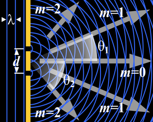
This is a drawing explaining two-slit diffraction: Planar wavefronts with wavelength λ (straight, vertical blue lines in the left-hand side of the image) arrives from the left at a barrier (thick yellow line) which have two slits or holes in it, at a distance d from each other. On the right-hand side of the barrier, the circular wavefronts that "leak" through the slits interfere with one another. This causes the light to scatter so that in certain directions, called orders (gray arrows labeled m0, m1, and m2), the light "concentrates" in beams while little or no light is emitted in the directions in between these orders. This image was rendered using the Persistence Of Vision Raytracer (POV-Ray for short) and the image description below. Note that to render this image, your POV-Ray installation needs to have access to the TrueType™ fonts timesbi.ttf (Times New Roman, bold & italic), timesbd.ttf (Times New Roman, bold), and symbols.ttf (various symbols, including greek letters), in order to render the white letters and numbers shown in the image. |
| 日期 | 2005年十二月25日 (原始上傳日期) |
| 來源 | 无法识别来源。根据版权声明推断为其自己的作品。 |
| 作者 | 无法识别作者。根据版权声明推断作者为Peo~commonswiki。 |
授權條款

|
已授權您依據自由軟體基金會發行的無固定段落、封面文字和封底文字GNU自由文件授權條款1.2版或任意後續版本,對本檔進行複製、傳播和/或修改。該協議的副本列在GNU自由文件授權條款中。 |
| 此檔案採用共享創意 姓名標示-相同方式分享 3.0 未在地化版本授權條款。 | ||
| ||
| 已新增授權條款標題至此檔案,作為GFDL授權更新的一部份。 |
Image description for use in POV-Ray
 /*
 ================================================
 Two-Slit Diffraction
 ------------------------------------------------
 Created by Søren Peo Pedersen - see my user page
 at http://da.wikipedia.org/wiki/Bruger:Peo
 ================================================
 */

 #declare WavefrontColor=<.2,.4,1>; // Wavefronts (default: blue)
 #declare BarrierColor=<1,.8,.2>;   // Barrier (default: Yellow)

 union { // The barrier with two slits in it:
   box {<-.1,.6,-.01>,<.1,5,.01>}    // Part above the slits
   box {<-.1,-.4,-.01>,<.1,+.4,.01>} // Part between the slits
   box {<-.1,-5,-.01>,<.1,-.6,.01>}  // Part below the slits
   pigment {color rgb BarrierColor} finish {ambient 1}
   }

 #local Cnt=1;   // Loop that puts some wavefront lines
 #while (Cnt<5)  // to the left of the barrier
   cylinder {<(.5-Cnt)*0.37,-5,0>,<(.5-Cnt)*0.37,5,0>,.02
   pigment {color rgb WavefrontColor} finish {ambient 1}}
   #local Cnt=Cnt+1;
 #end

 // Arrows to indicate the directions of diffraction orders:
 #macro OrderArrow(Start,End,Direction)  // Macro to render one arrow
   union {
     triangle {<End,0,.01>,<End-1,-.3,.01>,<End-1,.3,.01>}     // Forms an arrow
     triangle {<End-1,-.1,.01>,<End-1,.1,.01>,<Start,.1,.01>}  // stretching from
     triangle {<End-1,-.1,.01>,<Start,.1,.01>,<Start,-.1,.01>} // Start to End a-
     pigment {color rgb .6}                                    // long the +X ax-
     finish {ambient 1}                                        // is, then turns
     rotate <0,0,Direction>                                    // it to Direction
     }
 #end
 // Use the above macro to indicate 0th thru 2nd order diffraction:
 #object {OrderArrow(1.3,3.3,47.73141557)}   // 2nd order upwards
 #object {OrderArrow(1,5.7,21.71561728)}     // 1st order upwards
 #object {OrderArrow(.5,5.4,0)}              // 0th order horizontal
 #object {OrderArrow(1,5.7,-21.71561728)}    // 1st order downwards
 #object {OrderArrow(1.3,3.3,-47.73141557)}  // 2nd order downwards

 // "m=(number)" legends at each diffraction order
 #macro Mlig(Number) // Macro to render "m=" in bold italic, followed
   union {           // by the given Number in bold non-italic
     text {ttf "timesbi.ttf" "m=",.01,0}
     text {ttf "timesbd.ttf" str(Number,0,0),.01,0 translate <1.4,0,0>}
     pigment {color rgb 1}
     finish {ambient 1}
     scale .6
     translate <0,0,-.2>
     }
 #end
 // Use the above macro to label each order of diffraction:
 #object {Mlig(2) translate <.3,1.95,0>}   // 2nd opder upwards
 #object {Mlig(1) translate <3.1,1.8,0>}   // 1st order upwards
 #object {Mlig(0) translate <4,-.65,0>}    // 0th order
 #object {Mlig(1) translate <3.1,-2.1,0>}  // 1st order downwards
 #object {Mlig(2) translate <.3,-2.3,0>}   // 2nd order downwards

 // Angle-measuring "arcs" to indicate angles of diffraction:
 #macro Angle(Degrees,Index,Radius)
   union {
     difference {  // The arc part:
       cylinder {<0,0,-.1>,<0,0,-.11>,Radius}        // A cylinder, whose cur-
       plane {<0,Degrees,0>,0}                       // ved surface defines the
       plane {<0,-Degrees,0>,0 rotate <0,0,Degrees>} // arc, then parts of it
       pigment {                                     // are cut away using pla-
         cylindrical                                 // ne. Then it gets a cy-
         color_map {                                 // lindrical pigment thats
           [0 color rgbt <1,1,1,0.5>]                // transparent at the cen-
           [0.2 color rgbt <1,1,1,0.75>]             // ter so you only see it
           [1 color rgbt <1,1,1,1.0>]                // out near the curved
           }                                         // part.
         rotate <90,0,0>
         scale Radius
         }
       finish {ambient 1}
       }
     union { // "Nametag"; Greek "theta" with the given Index number:
         text {ttf "symbol.ttf","q",0.1,0 pigment {color rgb 1} finish {ambient 1} scale .6 translate <-.2,-.2,0>}
         text {ttf "timesbd.ttf",str(Index,0,0),0.1,0 pigment {color rgb 1} finish {ambient 1} scale .4 translate <.1,-.3,0>}
         translate <(Radius+.3)*cos(radians(Degrees/2)),(Radius+.3)*sin(radians(Degrees/2)),-.2>
         }
     }
 #end
 // Use the above macro to indicate the angles of diffraction:
 #object {Angle( 21.71561728,1,3)}   // Show 1st order diffraction angle upwards
 #object {Angle(-47.73141557,2,1.6)} // Show 2nd order diffraction angle downwards

 #local Hole=-.5;  // Loop run twice; once for
 #while (Hole<1)   // each slit in the barrier.
   box {<-.6,Hole-.02,-.2>,<-.2,Hole+.02,-.1>                  // Little lines and
     pigment {color rgb 1} finish {ambient 1}                  // triangular arrow-
     }                                                         // heads showing the
   triangle {                                                  // distance between
     <-.5,Hole*.98,-.2>,<-.4,Hole*.5,-.2>,<-.6,Hole*.5,-.2>  // the two slits in
     pigment {color rgb 1} finish {ambient 1}                // the barrier.
     }

   #local Cnt=1;   // Loop run "several" (20) times to render concentric
   #while (Cnt<20) // wavefronts emanating from each slit in the barrier:
     difference {
       torus {(Cnt-.5)*0.37,.02}   // Torus to form the arc, minus a plane to
       plane {<1,0,0>,.1}            // cut away part of arc left of the barrier
       pigment {color rgb WavefrontColor} finish {ambient 1}
       rotate <90,0,0> translate <0,Hole,0>
       }
     #local Cnt=Cnt+1;
   #end
   #local Hole=Hole+1;
 #end

 union { // Various letters and arrowheads:
   text {ttf "timesbi.ttf","d",0.1,0     // The "d" representing the distance
     scale .6 translate <-.66,-.2,-.2>}  // between the slits in the barrier
   text {ttf "symbol.ttf","l",0.1,0      // Greek letter "lambda" representing
     scale .6 translate <-.89,1.5,-.2>}   // the wavelength
   triangle {<-0.525,1.7,0>,<-0.325,1.6,0>,<-0.325,1.8,0>} // Arrowheads left and
   triangle {<-0.955,1.7,0>,<-1.155,1.6,0>,<-1.155,1.8,0>} // right of "lambda"
   pigment {color rgb 1} finish {ambient 1}
   }

 camera {  // Viewpoint:
   orthographic        // No perspective
   location <2.1,0,-5> // Looking from this position
   look_at <2.1,0,0>   // Looking towards this position
   }
檔案歷史
點選日期/時間以檢視該時間的檔案版本。
| 日期/時間 | 縮圖 | 尺寸 | 用戶 | 備註 | |
|---|---|---|---|---|---|
| 目前 | 2005年12月25日 (日) 12:45 | | 1,280 × 1,024(291 KB) | Peo~commonswiki | This is a drawing explaining two-slit diffraction: Planar wavefronts with wavelength ''λ'' (straight, vertical blue lines in the left-hand side of the image) arrives from the left at a barrier (thick yellow line) which have two slits or holes in it |
檔案用途
下列2個頁面有用到此檔案:
全域檔案使用狀況
以下其他 wiki 使用了這個檔案:
- ar.wikipedia.org 的使用狀況
- az.wikipedia.org 的使用狀況
- beta.wikiversity.org 的使用狀況
- bg.wikipedia.org 的使用狀況
- ca.wikipedia.org 的使用狀況
- cv.wikipedia.org 的使用狀況
- cy.wikipedia.org 的使用狀況
- da.wikipedia.org 的使用狀況
- da.wikibooks.org 的使用狀況
- en.wikipedia.org 的使用狀況
- en.wikibooks.org 的使用狀況
- eo.wikipedia.org 的使用狀況
- es.wikipedia.org 的使用狀況
- et.wikipedia.org 的使用狀況
- fa.wikipedia.org 的使用狀況
- fa.wikibooks.org 的使用狀況
- fi.wikipedia.org 的使用狀況
- fr.wikipedia.org 的使用狀況
- fr.wikibooks.org 的使用狀況
- gl.wikipedia.org 的使用狀況
- he.wikipedia.org 的使用狀況
- hi.wikipedia.org 的使用狀況
- hu.wikipedia.org 的使用狀況
- id.wikipedia.org 的使用狀況
- ja.wikibooks.org 的使用狀況
- kk.wikipedia.org 的使用狀況
- ko.wikipedia.org 的使用狀況
- lt.wikipedia.org 的使用狀況
- lv.wikipedia.org 的使用狀況
- mn.wikipedia.org 的使用狀況
- nl.wikipedia.org 的使用狀況
- pt.wikipedia.org 的使用狀況
- ro.wikipedia.org 的使用狀況
- ru.wikipedia.org 的使用狀況
- scn.wikipedia.org 的使用狀況
檢視此檔案的更多全域使用狀況。