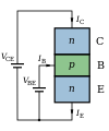
File:NPN BJT - Structure & circuit.svg
外觀

此 SVG 檔案的 PNG 預覽的大小:250 × 300 像素。 其他解析度:200 × 240 像素 | 400 × 480 像素 | 640 × 768 像素 | 853 × 1,024 像素 | 1,707 × 2,048 像素。
原始檔案 (SVG 檔案,表面大小:250 × 300 像素,檔案大小:19 KB)
檔案歷史
點選日期/時間以檢視該時間的檔案版本。
| 日期/時間 | 縮圖 | 尺寸 | 使用者 | 備註 | |
|---|---|---|---|---|---|
| 目前 | 2010年8月2日 (一) 06:03 |  | 250 × 300(19 KB) | Inductiveload | make colours and symbols match other images |
| 2010年8月2日 (一) 05:43 |  | 250 × 300(19 KB) | Inductiveload | fix transparency | |
| 2010年8月2日 (一) 05:42 |  | 250 × 300(19 KB) | Inductiveload | {{Information |Description={{en|1=A diagram of the structure of an NPN BJT, showing the collector-emitter voltage (''V''<sub>CE</sub>), base-emitter voltage (''V''<sub>BE</sub>) and the collector, base and emitter currents and directions (''I''<sub>C</sub |
檔案用途
下列頁面有用到此檔案:
全域檔案使用狀況
以下其他 wiki 使用了這個檔案:
- en.wikipedia.org 的使用狀況
- pt.wikipedia.org 的使用狀況
- sv.wikipedia.org 的使用狀況
- ta.wikipedia.org 的使用狀況

