
用户:Graywolf~zhwiki/sandbox
前言[编辑]
- 2011/11/24, 开启我人生的里程碑, 目前从事视讯会议, 负责VideoPhone的部分
X264vfw(Video For Windows)[编辑]
版本 : x264vfw_34_2008bm_29021
参考网址 : http://sourceforge.net/projects/x264vfw/files/x264vfw/
Encode[编辑]
Command Line[编辑]
- Command :--preset ultrafast --tune zerolatency --keyint 300 --scenecut 40 --ipratio 1.0 --qcomp 0.3 --cplxblur 30 --aq-mode 1 --qpstep 8 --deblock 1:-1
- ultrafast : 设定之后会盖掉前面的参数, 因此需要优先设定
             --no-8x8dct --aq-mode 0 --b-adapt 0
             --bframes 0 --no-cabac --no-deblock
             --no-mbtree --me dia --no-mixed-refs
             --partitions none --rc-lookahead 0 --ref 1
             --scenecut 0 --subme 0 --trellis 0
             --no-weightb --weightp 0
- zerolatency :
             --bframes 0 --force-cfr --no-mbtree
             --sync-lookahead 0 --sliced-threads
             --rc-lookahead 0
- 参数 :
       --keyint 300(每300個Frame會有一個I-Frame), 預設250
       --scenecut 40(設定決策使用I幀、IDR幀的閾值(場景變換檢測), 預設40
       --ipratio 1.0(修改I幀量化值相比P幀量化值的目標平均增量。越大的值會提高I幀的品質), 預設1.4
       --qcomp 0.3(量化值曲線壓縮係數。0.0是固定位元率,1.0則是固定量化值), 預設0.6
       --cplxblur 30(以給定的半徑範圍套用高斯模糊(gaussian blur)於量化值曲線。這意味著分配給每個幀的量化值會被它的鄰近幀模糊掉,
                     以此來限制量化值波動), 預設20
       --aq-mode 1(彈性量化模式), 預設1
       --qpstep 8(設定兩幀之間量化值的最大變更幅度), 預設4
       --deblock 1:1(參考網路上的設定), 預設0:0

       --subme 5(圖層變化細緻度, 在Pic1的A點(10, 10.25)移動到Pic2的B點(10, 12.27); 若subme設為0, 則紀錄該點的偏移量為(0,2),
                 若設為1, 則紀錄該點的偏移量為(0, 2.0), 2則紀錄該點的偏移量為(0, 2.02); 也就是subme越大影像越細膩), 預設7
- 心得 : 由于发现当I-Frame在传送的时候, 所设定的Bitrate会飙高(1.5~2倍, 视场景而定), 因此希望借由X264的参数来稳定带宽. 尝试用过vbv(Video Buffering Verifier), 虽可达到准确的带宽控制, 但是却抑制了I-Frame该有的资料量, 导致I相当于P来的丑(模糊)许多而无法接受
       --vbv-maxrate Bitrate(填滿Buffer的位元率, 越大則頻寬衝的越高), 預設0
       --vbv-bufsize Bitrate/2(Buffer的大小, 也可以說是Delay Time, 以Bitrate 512kbps來講, 若bufize 512, 則Delay 1秒),
                             預設0
Decode[编辑]
Video[编辑]
Capture[编辑]
Display[编辑]
DirectX(9.0)[编辑]
- 格式转换
由于Decode出来的影像格式为VY12, 但不是所有的显卡都能支援此格式; 因此我们将YV12转换成大多数显卡所能绘致的RGB32格式
- 传统转换公式:
- YV12 to RGB24:
- bool YV12_to_RGB24_table(unsigned char* pYV12, unsigned char* pRGB24, int Width, int Height)
- {
- if(!pYV12 || !pRGB24)
- return -1;
- if(!pYV12 || !pRGB24)
- const long nYLen = long(Width * Height);
- const int nHfWidth = (Width >> 1);
- if((nYLen < 1) || (nHfWidth < 1))
- return -1;
- if((nYLen < 1) || (nHfWidth < 1))
- // Y data
- unsigned char* yData = pYV12;
- // v data
- unsigned char* vData = &yData[nYLen];
- // u data
- unsigned char* uData = &vData[nYLen >> 2];
- if((!uData) || (!vData))
- return -1;
- if((!uData) || (!vData))
- int rgb[3];
- int i, j, m, n, x, y, pu, pv, py, rdif, invgdif, bdif;
- m = -Width;
- n = -nHfWidth;
- bool addhalf = true;
- for(y = 0; y < Height; y++)
- {
- m += Width;
- if(addhalf)
- {
- n += nHfWidth;
- addhalf = false;
- }
- else
- {
- addhalf = true;
- }
- for(x = 0; x < Width; x++)
- {
- i = m + x;
- j = n + (x >> 1);
- py = yData[i];
- // search tables to get rdif invgdif and bidif
- rdif = Table_fv1[vData[j]]; // fv1
- invgdif = Table_fu1[uData[j]] + Table_fv2[vData[j]]; // fu1+fv2
- bdif = Table_fu2[uData[j]]; // fu2
- rgb[2] = py+rdif; // R
- rgb[1] = py-invgdif; // G
- rgb[0] = py+bdif; // B
- j = nYLen - Width - m + x;
- i = (j << 1) + j;
- // copy this pixel to rgb data
- for(j = 0; j < 3; j++)
- {
- if((rgb[j] >= 0) && (rgb[j] <= 255))
- {
- pRGB24[i + j] = rgb[j];
- }
- else
- {
- pRGB24[i + j] = (rgb[j] < 0)? 0 : 255;
- }
- }
- }
- }
- return 0;
- }
- RGB24 to RGB32
- bool RGB24_to_RGB32(unsigned char* pRGB24, unsigned char* pRGB32, int Width, int Height)
- {
- for(int i = 0; i < Height ; i++) // RGB24转RGB32
- for(int i = 0; i < Height ; i++) // RGB24转RGB32
- {
- {
- for(int j = 0; j < Width ; j++)
- for(int j = 0; j < Width ; j++)
- {
- {
- pRGB32[(i * Width * 4) + (j * 4)] = pRGB24[(i * Width * 3) + (j * 3)];
- pRGB32[(i * Width * 4) + (j * 4)] = pRGB24[(i * Width * 3) + (j * 3)];
- pRGB32[(i * Width * 4) + (j * 4) + 1] = pRGB24[(i * Width * 3) + (j * 3) + 1];
- pRGB32[(i * Width * 4) + (j * 4) + 1] = pRGB24[(i * Width * 3) + (j * 3) + 1];
- pRGB32[(i * Width * 4) + (j * 4) + 2] = pRGB24[(i * Width * 3) + (j * 3) + 2];
- pRGB32[(i * Width * 4) + (j * 4) + 2] = pRGB24[(i * Width * 3) + (j * 3) + 2];
- pRGB32[(i * Width * 4) + (j * 4) + 3] = 0;
- pRGB32[(i * Width * 4) + (j * 4) + 3] = 0;
- }
- }
- }
- }
- return 0;
- return 0;
- }
- 2. 使用Surface转换:
- 设定被转换的参数(格式), CreateOffscreenPlainSurface
- 绘图
在绘图的部分采用Texture与Surface二种方式; 主要取决于来源的颜色格式
- 1. 建立装置CreateDevice(UINT Adapter, D3DDEVTYPE DeviceType, HWND hFocusWindow, DWORD BehaviorFlags, D3DPRESENT_PARAMETERS *pPresentationParameters, IDirect3DDevice9** ppReturnedDeviceInterface);
- /*
- Adapter, D3DADAPTER_DEFAULT
- DeviceType, D3DDEVTYPE_HAL 硬件绘制(GPU) or D3DDEVTYPE_SW 软件模拟绘制(CPU)
- hFocusWindow, 绘制视窗
- BehaviorFlags, 处理顶点方式 硬件(D3DCREATE_HARDWARE_VERTEXPROCESSING) 或软件(D3DCREATE_SOFTWARE_VERTEXPROCESSING) 或其他相关设定
- pPresentationParameters, 设定相关环境参数 例如Windowed(是否视窗模式) BackBufferFormat(资料格式) BackBufferWidth(资料宽度)...
- ppReturnedDeviceInterface, 储存DirectX Device的界面
- */
- 2. 设定绘制相关参数SetRenderState(D3DRENDERSTATETYPE State, DWORD Value);
- /*
- D3DRS_LIGHTING, 灯光控制
- D3DRS_ALPHABLENDENABLE, 透明贴图
- D3DRS_SRCBLEND, SRC混色模式
- D3DRS_DESTBLEND, DST混色模式
- D3DRS_BLENDOP, 混色模式
- D3DRS_CULLMODE, 指定画面描绘的模式
- */
- 3. 建立Texture CreateTexture(UINT Width, UINT Height, UINT Levels, DWORD Usage, D3DFORMAT Format, D3DPOOL Pool, IDirect3DTexture9** ppTexture, HANDLE* pHandle
);
- /*
- Width, 资料宽度
- Height, 资料高度
- Levels, 1 可借由GetLevelCount()来取得
- Usage, 0
- Format, 资料格式
- Pool, D3DPOOL_MANAGED 在系统内存建立一份备份 可以无视装置遗失
- ppTexture, 储存Texture元件
- pHandle, 0
- */
- 4. 建立顶点资讯 CreateVertexBuffer(UINT Length, DWORD Usage,DWORD FVF, D3DPOOL Pool, IDirect3DVertexBuffer9** ppVertexBuffer, HANDLE* pHandle);
- /*
- Length, 设定4个点座标长度即为4(需要再乘点座标资讯的结构大小)
- Usage, 0
- FVF, 设定顶点座标的环境 例如D3DFVF_XYZ 3维空间表示座标
- Pool, D3DPOOL_MANAGED 在系统内存建立一份备份 可以无视装置遗失
- ppVertexBuffer, 储存ppVertexBuffer元件
- pHandle, 0
- */
- CreateIndexBuffer(UINT Length, DWORD Usage, D3DFORMAT Format, D3DPOOL Pool, IDirect3DIndexBuffer9** ppIndexBuffer, HANDLE* pHandle);
- /*
- Length, 设定4个点座标长度即为4(需要再乘点座标资讯的结构大小)
- Usage, 0
- Format, D3DFMT_INDEX16(Indices are 16 bits each)
- Pool, D3DPOOL_MANAGED 在系统内存建立一份备份 可以无视装置遗失
- ppIndexBuffer, 储存ppIndexBuffer元件
- pHandle, 0
- */
- 5. 开始绘图
- Clear(DWORD Count, const D3DRECT *pRects, DWORD Flags, D3DCOLOR Color, float Z, DWORD Stencil);
- /*
- Count, 0
- pRects, NULL
- Color, D3DCLEAR_TARGET Clear the color
- Z, 1.0f
- Stencil, 0
- */
- BeginScene()
- SetTexture(DWORD Stage,IDirect3DBaseTexture9 *pTexture);
- /*
- Stage, 0 pTexture对应第0个
- pTexture, 储存pTexture元件
- */
- LockRect(UINT Level, D3DLOCKED_RECT *pLockedRect, CONST RECT *pRect, DWORD Flags);
- memcpy(pLockedRect->pBits, pData, size);
- UnlockRect(UINT Level)
- SetStreamSource(UINT StreamNumber, IDirect3DVertexBuffer9 *pStreamData, UINT OffsetInBytes, UINT Stride);
- /*
- StreamNumber, 0
- pStreamData, ppVertexBuffer
- OffsetInBytes, 0
- Stride, 座标资讯的结构大小
- */
- SetFVF(DWORD FVF);
- SetIndices(IDirect3DIndexBuffer9 *pIndexData);
- DrawIndexedPrimitive(D3DPRIMITIVETYPE Type, INT BaseVertexIndex, UINT MinIndex, UINT NumVertices, UINT StartIndex, UINT PrimitiveCount);
- /*
- Type, DrawIndexedPrimitive 照Index Buffer顺序画出三角形
- BaseVertexIndex, 0 从第0个顶点开始
- MinIndex, 0 最小的Index值为何
- NumVertices, 4 包含了几个点
- StartIndex, 0 从第BaseVertexIndex个点的第0的Index开始
- PrimitiveCount, 2 有2个Type
- */
- EndScene();
- Present(NULL, NULL, NULL, NULL);
- 贴字
OpenGL[编辑]
Color Space[编辑]
- 1. RGB24
- 每一个Pixel均是由相同位置的三个相同长宽的R, G, B平面所组成; 例如图片上的点P(a, b)是由三个平面R(a, b), G(a, b), B(a, b)所组成
- 2. YV12
- YV12影像格式的图片(Width, Height)是由Y(Width, Height), V(Width/2, Height/2), U(Width/2, Height/2)三个平面所组成, 大小及相对位置如图1.1~1.3
 例如YV12圖片上的點P(a, b)組成關係如下:
 P(0, 0)由Y(0, 0), V(0, 0), U(0, 0)所組成

 P(0, 1)由Y(0, 1), V(0, 0), U(0, 0)所組成

 P(1, 0)由Y(1, 0), V(0, 0), U(0, 0)所組成

 P(1, 1)由Y(1, 1), V(0, 0), U(0, 0)所組成
-
 图1.1 图片中Y的相对位置
 -
 图1.2 图片中V的相对位置
 -
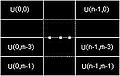 图1.3 图片中U的相对位置


- 内存排序的方式如图1.4, Y平面大小为Width * Height, V平面大小为Width/2 * Height/2, U平面大小为Width/2 * Height/2
- 3. I420
- I420影像格式的图片与YV12雷同(平面大小); 唯独差在V平面与U平面的内存位置, 也就是VU平面互换, 内存排序的方式如图2.1,
 例如YV12圖片上的點P(a, b)組成關係如下:
 P(0, 0)由Y(0, 0), U(0, 0), V(0, 0)所組成

 P(0, 1)由Y(0, 1), U(0, 0), V(0, 0)所組成

 P(1, 0)由Y(1, 0), U(0, 0), V(0, 0)所組成

 P(1, 1)由Y(1, 1), U(0, 0), V(0, 0)所組成
-
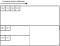 图2.1 I420, 内存排序方式

- 4. 转换
- 在Color Format转换上采用FFMpeg方式
- (1)YV12转YUY2
- SwsContext *img_convert_ctx;
- unsigned char *YUY2Buf;
- // Initialize
- img_convert_ctx = sws_getContext(Width, Height, PIX_FMT_YUV420P, Width, Height, PIX_FMT_YUYV422, SWS_POINT, NULL, NULL, NULL);
- // Transfer
- unsigned char *inbuf[3];
- unsigned char *outbuf[3];
- int inlinesize[3] = {Width, Width/2, Width/2};
- int outlinesize[3] = {Width* 2, 0, 0};
- inbuf[0] = (unsigned char* )malloc(Width * Height);
- inbuf[1] = (unsigned char* )malloc(Width * Height >> 2 );
- inbuf[2] = (unsigned char* )malloc(Width * Height >> 2);
- outbuf[0] = (unsigned char* )malloc(Width * mHeight * 2);
- outbuf[1] = NULL;
- outbuf[2] = NULL;
- memcpy(inbuf[0], YV12Buf, Width * Height);
- memcpy(inbuf[1], YV12Buf+ (Width * m_lVideoHeight), Width * Height >> 2);
- memcpy(inbuf[2], YV12Buf+ (Width * m_lVideoHeight*5>>2), Width * Height >> 2);
- sws_scale(img_convert_ctx, inbuf, inlinesize, 0, Height, outbuf, outlinesize);
- memcpy(YUY2Buf, outbuf[0], Width * Height * 2);
- free(*inbuf);
- free(*outbuf);
- // Release
- sws_freeContext(img_convert_ctx);
Audio[编辑]
RTP Info[编辑]
- 1. Marker bit & PayLoad type
- 我们可以借由RTP Header的第二BYTE来得到Marker bit及PayLoad type, Marker bit表示此封包为Frame的最后一个包也就是结尾; Video的PayLoad type为96 ~ 127
- unsigned char marker:1;
- unsigned char payloadtype:7;
- 我们可以借由RTP Header的第二BYTE来得到Marker bit及PayLoad type, Marker bit表示此封包为Frame的最后一个包也就是结尾; Video的PayLoad type为96 ~ 127
- 2. 指数Golomb码
- 在影像上, 我们较关切的如何取得长宽资讯, 在H264 bitstream中长宽资讯是以指数Golomb的编码方式存取; 而长宽资讯是编码在SPS(Sequence Parameter Set)中
- 指数Golomb码简易来说就是移动n个Bits后遇到"1", 即往后取n个Bits; 参数藉游编码所占的Bits数举例如下
- 占1Bit-> 1
- 占3Bit-> 01, 此参数的值占3Bits; 例如011, 移动1个Bit后遇到"1"因此往后多取1Bit, 值为"3", 010, 值为"2"
- 占5Bit-> 001, 此参数的值占5Bits; 例如00101, 移动2个Bit后遇到"1"因此往后多取2Bit, 值为"3"
- 占7Bit-> 0001, 此参数的值占7Bits; 例如0001011, 移动3个Bit后遇到"1"因此往后多取3Bit, 值为"11"
- 在影像上, 我们较关切的如何取得长宽资讯, 在H264 bitstream中长宽资讯是以指数Golomb的编码方式存取; 而长宽资讯是编码在SPS(Sequence Parameter Set)中
- 长宽资讯从Wireshark分析的话, 名称为"pic_width_in_mbs_minus1"与"pic_height_in_mbs_minus1"; 意思为取出的值+1在乘16即为该Frame的长宽