匹配Z变换方法


匹配Z变换方法(matched Z-transform method)也称为极点-零点映射(pole–zero mapping)[1][2]或极点-零点匹配法(pole–zero matching method)[3],简称MPZ或MZT[4],是将连续时间滤波器转换到离散时间滤波器(数字滤波器)设计的技巧。
其作法是将所有的s平面设计时的极点和零点转换到z平面的位置,其中取样周期[5]。因此以下传递函数的类比滤波器:
会转换为以下的数位传递函数
其增益需调整,使结果为其理想的增益,一般会和类比滤波器的直流增益匹配,透过设定及,并且求解.[3][6]。
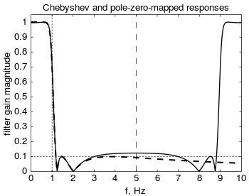
因为此映射会将s平面的轴反复的映射到z平面的单位圆上,若零点或是极点超过奈奎斯特频率,其映射后的位置会有混叠的情形[7]。
一般情形下,类比滤波器的极点会比零点多,在处的零点可以移到奈奎斯特频率,作法是放在的位置[1][3][6][7]。
此转换方式可以保持有界输入有界输出稳定性以及最小相位,但不会保持时域或是频域的响应,因此不常使用[8][7]。较常使用的方式有双线性转换及冲激不变法[4]。匹配Z变换方法的高频响应误差比双线性转换要小,因此比较容易透过加入额外的零点来修正其特性,此方式称为MZTi(i表示改良版improved)[9]。
在数位控制中,匹配Z变换方法有一个特别的应用,就是艾克曼公式,可以调整可控制性系统的极点,一般会将不稳定(或接近不稳定)的极点调整到稳定的位置。

参考资料[编辑]
- ^ 1.0 1.1 Won Young Yang. Signals and Systems with MATLAB. Springer. 2009: 292 [2018-10-19]. ISBN 978-3-540-92953-6. (原始内容存档于2017-09-20).
- ^ Bong Wie. Space vehicle dynamics and control. AIAA. 1998: 151 [2018-10-19]. ISBN 978-1-56347-261-9. (原始内容存档于2015-03-26).
- ^ 3.0 3.1 3.2 Arthur G. O. Mutambara. Design and analysis of control systems. CRC Press. 1999: 652 [2018-10-19]. ISBN 978-0-8493-1898-6. (原始内容存档于2019-07-30).
- ^ 4.0 4.1 Al-Alaoui, M. A. Novel Approach to Analog-to-Digital Transforms. IEEE Transactions on Circuits and Systems I: Regular Papers. February 2007, 54 (2): 338–350 [2018-10-19]. ISSN 1549-8328. doi:10.1109/tcsi.2006.885982. (原始内容存档于2018-06-04).
- ^ S. V. Narasimhan and S. Veena. Signal processing: principles and implementation. Alpha Science Int'l Ltd. 2005: 260 [2018-10-19]. ISBN 978-1-84265-199-5. (原始内容存档于2019-07-28).
- ^ 6.0 6.1 Franklin, Gene F. Feedback control of dynamic systems. Powell, J. David, Emami-Naeini, Abbas Seventh. Boston: Pearson. 2015: 607–611. ISBN 0133496597. OCLC 869825370.
Because physical systems often have more poles than zeros, it is useful to arbitrarily add zeros at z = -1.
- ^ 7.0 7.1 7.2 Rabiner, Lawrence R; Gold, Bernard. Theory and application of digital signal processing. Englewood Cliffs, New Jersey: Prentice-Hall. 1975: 224–226. ISBN 0139141014 (英语).
The expediency of artificially adding zeros at z = —1 to the digital system has been suggested ... but this ad hoc technique is at best only a stopgap measure. ... In general, use of impulse invariant or bilinear transformation is to be preferred over the matched z transformation.
- ^ Jackson, Leland B. Digital Filters and Signal Processing. Springer Science & Business Media. 1996: 262. ISBN 9780792395591 (英语).
although perfectly usable filters can be designed in this way, no special time- or frequency-domain properties are preserved by this transformation, and it is not widely used.
- ^ Ojas, Chauhan; David, Gunness. Optimizing the Magnitude Response of Matched Z-Transform Filters ("MZTi") for Loudspeaker Equalization. Audio Engineering Society. 2007-09-01 [2018-10-19]. (原始内容存档于2019-07-27) (英语).
| ||||||||||||||||||||||


